

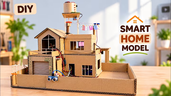
Project Demonstration Video
Watch the automated gate entry, rain roof shuttering, and real-time gas alarm response in action:
Architectural Overview: Why Dual Microcontrollers?
Modern domestic automation requires both deterministic hard real-time safety and frictionless cloud internet connectivity. Attempting to run high-speed motor sequencing, safety interrupts, and gas detection on a cloud-polled device often results in delayed responses whenever WiFi lags.
To solve this, our Smart House utilizes a decoupled Dual-MCU architecture:
- Subsystem A — Arduino UNO (Deterministic Safety & Automation):
- Gas Leak Sentry: Samples the gas sensor continuously. If LPG or combustible gases breach threshold levels, an active audio alarm triggers immediately via
BUZZER_PINwithout relying on network latency. - Smart Rain Roof: Continuously monitors the
YL-83raindrop sensor with debounce verification. When rain is confirmed, it commands a motorized awning roof to slide forward, shielding outdoor areas. - Intelligent Gate & Garage Shutter: Measures ultrasonic echo times. When an approaching vehicle reaches within , it coordinates a timed garage sequence: opens the main gate, lifts the roll-up shutter, pauses for vehicle parking, and then seals both barriers.
- Subsystem B — ESP32 (Cloud IoT Control via Blynk 2.0):
- Connects to home 2.4 GHz WiFi networks using the onboard ESP-WROOM-32 transceiver.
- Subscribes to the Blynk 2.0 IoT Cloud Platform to allow smartphone remote toggling of ambient lights via a 5V relay module and speed regulation of twin room ventilation fans via a dedicated L298N H-bridge driver.
Complete Circuit Schematic & Wiring Guide
Below is the verified connection schematic illustrating both the Arduino UNO automation wiring (left side) and the ESP32 Blynk IoT control circuit (right side).
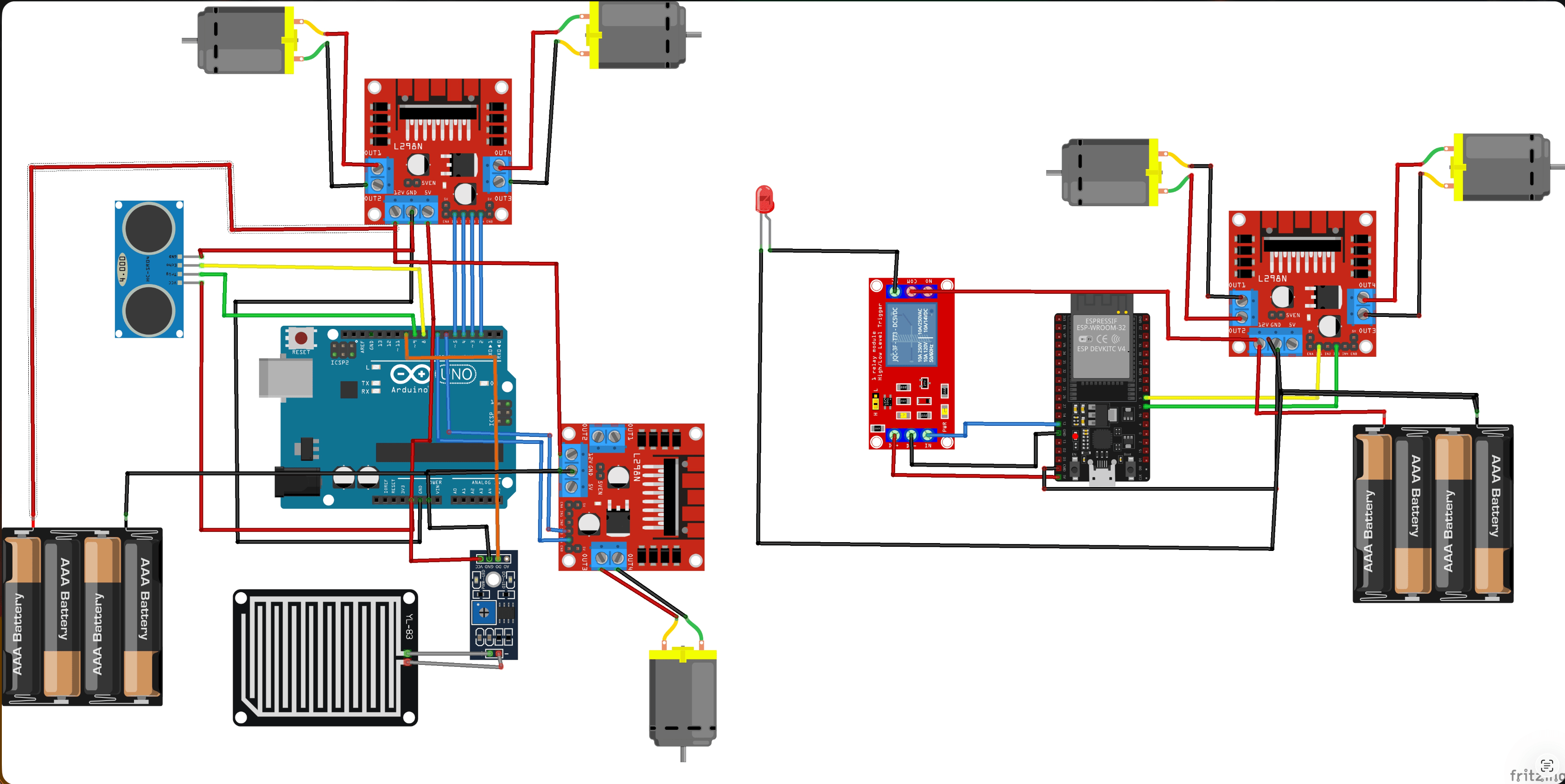
1. Arduino UNO Safety & Motor Pin Connections
| Arduino UNO Pin | Module / Sensor Pin | Description |
|---|---|---|
| Digital Pin 2 | Rain Sensor Digital Out (DO) | Active LOW rain presence signal from YL-83 comparator |
| Analog Pin A3 | MQ Gas Sensor Digital Out (DO) | Active LOW gas leak detection threshold |
| Digital Pin 4 | Active Piezo Buzzer Negative terminal | Active LOW alarm trigger (+ terminal tied to 5V) |
| Digital Pin 6 | HC-SR04 Ultrasonic TRIG | ultrasonic pulse trigger |
| Digital Pin 11 | HC-SR04 Ultrasonic ECHO | Ultrasonic flight-time pulse listener |
| Digital Pin 5 | L298N #1 GATE_ENA | PWM speed regulation for Main Gate motor |
| Digital Pin 7 | L298N #1 GATE_IN1 | Gate motor directional logic 1 |
| Digital Pin 8 | L298N #1 GATE_IN2 | Gate motor directional logic 2 |
| Digital Pin 9 | L298N #1 SHUTTER_ENB | PWM speed regulation for Garage Shutter |
| Digital Pin 10 | L298N #1 SHUTTER_IN3 | Garage Shutter directional logic 1 |
| Digital Pin 12 | L298N #1 SHUTTER_IN4 | Garage Shutter directional logic 2 |
| Digital Pin 3 | L298N #2 RAIN_ENA | PWM speed regulation for Rain Roof motor |
| Analog Pin A0 | L298N #2 RAIN_IN1 | Retractable roof directional logic 1 |
| Analog Pin A1 | L298N #2 RAIN_IN2 | Retractable roof directional logic 2 |
| 5V / GND | Sensors & Motor Logic GND | Shared reference ground and 5V sensor power bus |
2. ESP32 Blynk IoT Cloud Pin Connections
| ESP32 GPIO Pin | Module / Component Pin | Description |
|---|---|---|
| GPIO 23 | 1-Channel Relay IN | Active-LOW relay module switching main room light |
| GPIO 4 | L298N #3 FAN1_ENA | Hardware PWM speed channel for Room Fan 1 |
| GPIO 18 | L298N #3 FAN1_IN1 | Directional drive pin for Room Fan 1 |
| GPIO 5 | L298N #3 FAN1_IN2 | Ground return pin for Room Fan 1 |
| GPIO 2 | L298N #3 FAN2_ENB | Hardware PWM speed channel for Room Fan 2 |
| GPIO 16 | L298N #3 FAN2_IN3 | Directional drive pin for Room Fan 2 |
| GPIO 17 | L298N #3 FAN2_IN4 | Ground return pin for Room Fan 2 |
| GND | Battery Pack & Driver GND | Common Ground shared across battery and ESP32 |
GND) of the motor battery packs to the GND pin of the Arduino and ESP32 microcontrollers. A floating ground reference prevents logic signals from triggering the L298N optocouplers and causes erratic motor flutter!Mathematical Principle: Ultrasonic Distance Calculation
The HC-SR04 ultrasonic sensor measures time of flight for a acoustic chirp. The speed of sound through dry air at room temperature () is approximately , or .
Because the sound wave travels out to the incoming car and bounces back to the receiver, the total distance is calculated by halving the round-trip flight duration:
Where:
- is the vehicle proximity distance in centimeters ().
- is the microsecond pulse duration returned by
pulseIn(ECHO_PIN, HIGH, 30000). - A 30 ms timeout ensures that if no obstacle is detected, the function returns without blocking the microcontroller loop.
Firmware 1: Arduino UNO Autonomous Safety & Gate Controller
Save and flash this code to your Arduino UNO R3/R4 using the Arduino IDE (smart_house_arduino.ino):
Firmware 2: ESP32 Blynk IoT Cloud Firmware
Flash this code to your ESP32 DevKit board to connect your home lighting and twin ventilation fans to the Blynk IoT app (smart_house_esp32_blynk.ino):
Blynk IoT App Setup Guide
To control your lights and fans from your iOS or Android smartphone:
- Create Blynk 2.0 Template:
- Sign in at blynk.cloud and navigate to Templates → New Template.
- Set Hardware to
ESP32, Connection Type toWiFi.
- Configure Datastreams:
- V1 (Room Light): Data Type
Integer, Min0, Max1. - V2 (Fan 1 Speed): Data Type
Integer, Min0, Max255. - V3 (Fan 2 Speed): Data Type
Integer, Min0, Max255. - V4 (Master Cutoff): Data Type
Integer, Min0, Max1. - V5 (WiFi RSSI Signal): Data Type
Integer, UnitdBm.
- Build the Mobile Dashboard:
- Open the Blynk IoT app on your phone.
- Add a Button Widget bound to
V1(Mode: Switch) for the Main Room Light. - Add two Slider Widgets bound to
V2andV3(Range: 0–255) for Fans 1 and 2. - Add a Push Button Widget bound to
V4for the Master "Leaving Home" shutoff.
Testing & Calibration Checklist
- [ ] Gas Sensor Warmup: MQ-2 gas sensors need approximately 30–60 seconds of heater preheat time before their analog readings stabilize.
- [ ] Common Ground Check: Ensure the black GND wires from both battery holders, the Arduino UNO, and the ESP32 are all joined into a common GND rail on the breadboard.
- [ ] Ultrasonic Sightline: Mount the HC-SR04 sensor angled directly towards the driveway without reflecting off side walls to prevent premature gate triggering.
- [ ] Relay Polarity: If the light turns ON when Blynk displays OFF, flip the logic state in
BLYNK_WRITE(V1)to match your relay module's trigger polarity.